What is the differences between relay output and DC/AC output? Our Automation will tell you.
Relay output: In a switch where the contacts remain in one state unless actuated, the contacts can either be normally open (abbreviated “n.o.” or “no”) until closed by operation of the switch, or normally closed (“n.c.” or “nc”) and opened by the switch action. Our remote receiver can be grouped into two types according to its current output modes. They are normally open/closed switch connection or current direct output connection (Controlled device can get power from powered receiver directly).
One customer sent a picture of “Normally Open/Closed Receiver Connecting to an AC Lamp” to us to ask whether it is correct or not.

Unfortunately, it is a wrong wiring. Please see a red cross to the lamp wiring from the following picture. This red cross points out the wrong wiring. AC lamp should not wire to the normally open terminals of receiver because there is no current through them which are only equivalent to a switch.

The correct wiring is as follow. This is the 1 channel normally open/ closed ac receiver(S1U-AC220) wiring. AC lamp is connected to normally open terminals B&C. And add a wire between terminals B&N and another wire to terminals C&L. At last, wire a plug to terminals L&N. Then, we finish the wiring.


Another customer attempted to install the unit model: 0020483 (S1DA-AC220-ANT2 & CB-2) to time his water heater pump. Everything on the remote unit seems to work OK except that he cannot get voltage from the unit to the pump to make it run.
He installed the wires as follows:
From house/wall AC 120v power black (line) on L, white (neutral) on N.
TO the pump, Black (line) on B, and white (neutral) on C. Timer works fine, however with timer LED light on he get no voltage from A, B, or C. He has checked the terminals with a multi meter and there is no voltage out to the pump. Also he checked the continuity of the cord to the pump–it is OK.
Then why did water heater pump don’t work?
The answer is he didn’t wire the water heat pump correctly.
The receiver he bought is relay output, not AC power output. So the wiring is incorrect. He should also connect black (line) of AC 120v power to terminal C, connect terminal B to Black (line) of the pump, and connect white (neutral) of AC 120v power to white (neutral) of the pump.
Look at this picture, Model: 0020504 (S1U-DC12-ANT2 & CB-2L) , the receiver is relay output, not DC/AC output, the connection is definitely wrong; the lamps didn’t connect any power supply, so it can’t work.

Here is the circuit diagram.
Usually, when the receiver is relay output, the wiring operation should be as follow:
Connect DC power to terminal “+” and “-“.
Initial state of relay output terminals: Terminals B and C are Normally Open; Terminals A and B are Normally Closed.
Terminal B and C should also connect a DC/AC power supply to make the lamp work.


This is the correct connection.

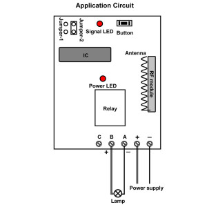
Model: 0020424 (S1X-DC06/09/12/24 & C-2) is DC power output, the wiring is easier compare to model:0020504 (S1U-DC12-ANT2 & CB-2L) , which is relay output
When choosing the DC power output unit, you just need to connect DC power to terminals “+” and “-”, and connect lamp to terminals “A” and “B”.
Here is the circuit diagram:

Generally speaking, the wiring differences between relay output and DC/AC output is that you should also connect a power supply to Normally Open terminal when your receiver is relay output model.
Online shop: www.ourautomation.com
没有评论:
发表评论