2015年9月3日星期四

How to Remote Control Electric Wolf Whistle Car Horn

Question from customer:
“I have a classic car with a 12 volt electric wolf whistle. I’d like to trip the wolf whistle from outside the car during cruise nights. How would I accomplish this?”
wolf whistle car horn
Answer:
We recommend the model of 6000ft 6V/9V/12V/24V power output remote control kit (S1X-DC06/09/12/24-ANT2 & CB-2). Usually, 12 volt is default voltage for this kit. If you input 12 volt power to that receiver, receiver will output 12 volt for your wolf whistle horn. It is easy to practice with using of rf remote control because rf signal has advantage of passing through doors, walls, trees as well as other obstacles and long distance transmitting. We add external extended antenna to extend the range of the remote controller and make its transmission distance reach 6000ft/2000m in the open field.
1_01_1
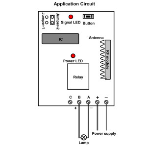
Wiring is very simple. You can wire your wolf whistle horn to output terminals of receiver directly.
The outputs from the receiver can drive relay connected to your wolf whistle horn. Your device will work.
circuit
Usage:
Setting different control modes (We have set the receiver as Toggle mode before delivery. If you want to use other modes, do as following):
1) Setting control mode Toggle: Only connect Jumper-2.
Press big button: Turn on the relay, terminal A&B output DC power.
Press big button again: Turn off the relay, terminal A&B no output.

2) Setting control mode Momentary: Only connect Jumper-1.
Press and hold big button: Turn on the relay, terminal A&B output DC power.
Release big button: Turn off the relay, terminal A&B no output.

3) Setting control mode Latched: Do not connect Jumper-1 and Jumper-2.
Press big button: Turn on the relay, terminal A&B output DC power.
Press small button: Turn off the relay, terminal A&B no output.

General speaking, you can set Momentary mode for wolf whistle horn. When you press a momentary button, your wolf whistle horn stays on as long as you maintain pressure on the button. When you stop maintaining pressure on the button, your wolf whistle horn stops sounding.

Portable Jack is Operated Remotely by 2000m AC Time Delay Remote Module

Question from customer:
I want a transmitter and receiver (2 remote distance 1000m) for operating a portable jack with a timer 20 minutes.
portable-jack
Answer:         
We recommend the model : 1 channel long distance remote module with adjustable timer (S1DA-AC220-ANT2 & CB-2). This module includes two parts: one is transmitter, the other is receiver. We add external extended antenna to make their transmission distance reach 2000m when transmitter separate from receiver. This kind of controller uses radio frequency to send signals. These signals are transmitted at a particular frequency. A receiver can receive those signals only if it is configured for that frequency. It can realize time delay function because we insert timer on the PCB board. Timer is adjustable from 0 second~99 hours. You can set time freely as you want.
1_01_1
Here is the wiring. We will wire portable jack to B&C dry contact terminals. A wire is connected to B &N terminals. Another wire is connected C&L terminals. At last, we add power to receiver.
circuit
Press buttons of “+”and “-” on the timer, adjust delay time from 0 second to 99 hours. “H” is Hour, “M” is Minute, and “S” is Second. For example, you want to set 20 minutes delay time. You set “M 2 0”. In order to check control module’s working statues, we can plug a lamp to that jack.
Press big button: Turn on jack and turn on lamp (connect B and C, disconnect A and B).
After delay time: Turn off jack by itself, then lamp will off latter (disconnect B and C, connect A and B).
Press small button: Turn off jack immediately, no need to wait for delay time. Lamp is also off at once.

RF Momentary Vibration Receiver and two 1000m RF Transmitters Application

Question from customer:
I am interesting of buying 2 receivers with one transmitter with the higher actual distance. I want with one transmitter to control separate these two receivers which will be in the same place. I want also only vibration mode and when I press and hold the button the receiver start vibrate until I release the transmitter’s button. Please suggest me a kit for my needs.
Answer:
We recommend two vibration receivers (Z-04) and one long range transmitter  (CB-2). It can realize wireless control when it pairs with transmitter from any place within a reliable distance; the wireless signal can pass many obstacles like walls, doors and doors. It is only vibration mode in that receiver. Those two gadgets will be configured in advance so that they can work together.
transmitter&vibrator_1inner circuit
If you want better working range, you can choose external antenna for these two receivers Z-04. The kit’s transmission distance can reach 2000m/6000ft in the open field.
add external antenna

Usage:
1 Press and hold big button, the receiver 1 vibrates.
2 Release big button, the receiver 1 stops vibrating.
3 Press and hold small button, the receiver 2 vibrates.
4 Release small button, the receiver 2 stops vibrating.

RC Transmitter and Receiver Operates Lawnmower Actuator

Question from customer:
I’m looking for an RC transmitter and receiver to operate the 4″ actuator a distance of 200ft for steering a lawnmower. Any suggestions?
700-590742
Answer:
We recommend the model of 500m/1500ft RF motor controller (S1FC-DC09/12/24 & CV-4-2). The controller is activated by DC 9V, 12V and 24V. It is usually for motors of rolling blinds, doors, projection screens, awnings, pumps, winches, conveyor or other appliances and mechanicals. It features in forward-reverse-stop capability which can make motor rotate in positive or reversal direction. With maximum transmission distance of 500m/1500ft, it can satisfy your requirement. Inner circuit of this kit uses the RF technology for making a wireless remote, which can make motor controlled by transmitter from any places with in reliable distance, this configured wireless signal can pass through walls, doors or floors or other solid obstacles.
1_13_1
Here is the wiring.
At first, we connect power line to terminals “+” and “-”. Secondly, we connect the receiver to the lawnmower actuator motor. Lawnmower actuator motor is wired to UP and DOWN terminals of receiver. At last, we add power supply to receiver. You can exchange “UP” and “DOWN” lines of the motor to change rotating direction of the motor.
1_06
There two working modes in it.
Set Momentary control mode: Do not connect Jumper.
Press and hold button ▲ on remote or receiver: Terminals UP and DOWN output + DC9V / DC12V / 24V (UP: +, DOWN: -), lawnmower actuatormotor rotates continuously in positive direction.
Release button ▲ on remote or receiver: Stop the motor.
Press and hold button ▼ on remote or receiver: Terminals UP and DOWN output - DC9V / DC12V / 24V (UP: -, DOWN: +), lawnmower actuatormotor rotates continuously in reversal direction.
Release button ▼ on remote or receiver: Stop the motor.

Set Latching control mode: connect the Jumper.
Press button ▲ on remote or receiver: Terminals UP and DOWN output + DC9V / DC12V / 24V (1: +, 2: -), lawnmower actuatormotor rotates continuously in positive direction.
Press ■ on remote or receiver: Stop the motor.
Press button ▼ on remote or receiver: Terminals UP and DOWN output - DC9V / DC12V / 24V (1: -, 2: +), lawnmower actuatormotor rotates continuously in reversal direction.
Press button ■ on remote or receiver: Stop the motor.

Remote Control Electric Hoist

Question from customer:
“I’d like to order a 220v electric hoist to raise and down a bridge boat with a remote control.
The ascent and descent should be done when someone is still pressing the remote control button, as there is no stop. What would you like me the most suitable product? Thank you in advance.”
electric hoist
Answer:
We recommend the ac 100V~240V momentary motor controlling model (S1FM-AC220 & CV-2-2). It is specially designed for motor controlling because two relays are inserted inside. One relay is used for motor rotating towards “UP”. Another relay is used for motor rotating towards “DOWN”. There are “UP”, “COM” and “DOWN” contacts from output terminal. This kit can controls motor of rolling blinds, doors, projection screens, awnings, pumps, conveyors other appliances and mechanicals. The transmitting distance is usually about 500m in the open air.
motor controller
Wiring:
Connect live wire to terminal “L” and neutral wire to terminal “N”. Then connect AC electric hoist motor to terminals “UP”, “COM” and ‘DOWN”. You can exchange “UP” and “DOWN” wires of motor to change rotating direction of motor.
wiring
Operation:
There are three buttons on the receiver for motor up and down. But button ■ on the receiver is useless.
Press and hold button ▲ on remote or receiver: Terminals UP and COMMON directly output AC110V / AC220V; electric hoist motor rotates continuously in positive direction.
Release button ▲ on remote or receiver: Stop the electric hoist motor.

Press and hold button ▼ on remote or receiver: Terminals DOWN and COMMON directly output AC110V / AC220V; electric hoist motor rotates continuously in reversal direction.
Release button ▼ on remote or receiver: Stop the electric hoist motor.

2015年9月2日星期三

Relay output different from DC/AC output

What is the differences between relay output and DC/AC output? Our Automation will tell you.
Relay output: In a switch where the contacts remain in one state unless actuated, the contacts can either be normally open (abbreviated “n.o.” or “no”) until closed by operation of the switch, or normally closed (“n.c.” or “nc”) and opened by the switch action. Our remote receiver can be grouped into two types according to its current output modes. They are normally open/closed switch connection or current direct output connection (Controlled device can get power from powered receiver directly).
One customer sent a picture of “Normally Open/Closed Receiver Connecting to an AC Lamp” to us to ask whether it is correct or not.


Unfortunately, it is a wrong wiring. Please see a red cross to the lamp wiring from the following picture. This red cross points out the wrong wiring. AC lamp should not wire to the normally open terminals of receiver because there is no current through them which are only equivalent to a switch.


The correct wiring is as follow. This is the 1 channel normally open/ closed ac receiver(S1U-AC220) wiring. AC lamp is connected to normally open terminals B&C. And add a wire between terminals B&N and another wire to terminals C&L. At last, wire a plug to terminals L&N. Then, we finish the wiring.


Another customer attempted to install the unit model: 0020483 (S1DA-AC220-ANT2 & CB-2) to time his water heater pump. Everything on the remote unit seems to work OK except that he cannot get voltage from the unit to the pump to make it run.
He installed the wires as follows:
From house/wall AC 120v power black (line) on L, white (neutral) on N.
TO the pump, Black (line) on B, and white (neutral) on C. Timer works fine, however with timer LED light on he get no voltage from A, B, or C. He has checked the terminals with a multi meter and there is no voltage out to the pump. Also he checked the continuity of the cord to the pump–it is OK.
Then why did water heater pump don’t work?
The answer is he didn’t wire the water heat pump correctly.
The receiver he bought is relay output, not AC power output. So the wiring is incorrect. He should also connect black (line) of AC 120v power to terminal C, connect terminal B to Black (line) of the pump, and connect white (neutral) of AC 120v power to white (neutral) of the pump.
Look at this picture, Model: 0020504 (S1U-DC12-ANT2 & CB-2L) , the receiver is relay output, not DC/AC output, the connection is definitely wrong; the lamps didn’t connect any power supply, so it can’t work.


Here is the circuit diagram.
Usually, when the receiver is relay output, the wiring operation should be as follow:
Connect DC power to terminal “+” and “-“.
Initial state of relay output terminals: Terminals B and C are Normally Open; Terminals A and B are Normally Closed.
Terminal B and C should also connect a DC/AC power supply to make the lamp work.


This is the correct connection.


Model: 0020424 (S1X-DC06/09/12/24 & C-2) is DC power output, the wiring is easier compare to model:0020504 (S1U-DC12-ANT2 & CB-2L) , which is relay output
When choosing the DC power output unit, you just need to connect DC power to terminals “+” and “-”, and connect lamp to terminals “A” and “B”.
Here is the circuit diagram:


Generally speaking, the wiring differences between relay output and DC/AC output is that you should also connect a power supply to Normally Open terminal when your receiver is relay output model.
Online shop:  www.ourautomation.com

2015年9月1日星期二

Adjustable Time Delay Wireless Control Kit for Reversible Motor

Adjustable Time Delay Wireless Control Kit for Reversible Motor
Reversible motor is a motor in which the direction of rotation can be reversed by means of a switch that changes motor connections when the motor is stopped. If you want to control a DC reversible motor, you may choose a wireless remote control kit.
Model 0020320 (S2DA-DC12 & C-4) is a wireless remote control kit with adjustable time delay function which is work for DC Equipments. The receiver model 0020319 (S2DA-DC12) is 2 channels and input voltage is DC 12V. It is an adjustable time delay control mode. Adjustable delay time can be 0 second – 99 hours. The transmitter model 0021003 (C-4) has 4 buttons and has a sliding cover which can protect the button when you slide the cover up.
With such combination, you can easily complete two operations at the same time. For example, turn the light on and open the door in the meantime. Applications include gate remote control, motor remote control, garage door remote control, light remote control, etc.

 Here is an application that you can use this kind of kit to control a DC reversible motor:
One of our customers wants to use a wireless remote control kit to control a DC12V motor. The kit should have the following function: When press the button 1 of the transmitter, the motor is in forward direction, then it will stop automatically after delay 12 seconds. When press the button 2 of the transmitter, the motor is in reverse direction, after 12 seconds delayed time it will turn back to the starting point and stop automatically. Then we recommended him Model 0020320 (S2DA-DC12 & C-4).


First of all, let’s see material preparation.
1 x 2 channel adjustable time delay remote control receiver (S2DA-DC12)
  2 x 4-button remote transmitter(C-4)
  2 x DC12v power adapters
1 x DC12V motor
  Some lines


Secondly, see the wiring diagram below, C is normally open terminal; A is normally closed terminal and B is common terminal. Connect terminal A to the negative pole and connect terminal C to the positive pole. Terminal B is supposed to be connected to the motor.
Note: The Power supply of receiver and motor must be provided individually in order to avoid interference between them.

Operation:
Press button 1, relay 1 turns on, the motor rotates in forward direction;
After delay time: The relay 1 will turn off by itself.
Press button 3, motor stops rotating (No need to wait for delay time).


Press button 2, relay 2 turns on, the motor rotates in reverse direction;
After delay time: The relay 2 will turn off by itself.
Press button 4, motor stops rotating (No need to wait for delay time).


You may ask how to set the delay time, do as followings:
Press buttons of “+” and “-” on the timer, adjust delay time from 0 second to 99 hours. Two buttons of Timer 1 adjust delay time of relay 1; two buttons of Timer 2 adjust delay time of relay 2. H is Hour, M is Minute, and S is Second.
In the above case, the customer may set “1 2 S 1 2” on Timer, it means the delay time on Timer 1 is 12 seconds, the delay time on Timer 2 is 12 seconds. Then he can achieve the whole operation.

The receiver model 0020319 (S2DA-DC12):


The transmitter model 0021003 (C-4):


The wireless remote control kit model 0020320 (S2DA-DC12 & C-4):