2015年11月18日星期三

Wireless DC Motor Remote Controller & Digital Screen Speed Governor for adjusting the Speed of Motor Rotation

Wireless DC Motor Remote Controller & Digital Screen Speed Governor for adjusting the Speed of Motor Rotation  
We introduce the new product here: wireless DC motor remote controller DC motor speed governor. The controller’s model is: 0020412 (S1XT-DC06/09/12/24 & C-1). The Speed Governor’s model is 0044001.The wireless DC motor control system can remote control motor rotation and the speed governor with digital screen can adjust the speed of motor rotation. The speed governor’s speed adjustment range is 0~100%. That means twist the “Adjustable potentiometer” in the speed governor, when the screen display digital “0”, the motor stop rotating; when the screen display digital “1 ~100”, the motor rotating. And the higher the number, the faster rotation. When the screen display digital “100”, that means the speed of motor rotation is fastest. You can connect the DC motor controller and DC motor to speed governor, then use the transmitter to remote control motor rotation.  
                 1
1  
Here is the circuit diagram of the wireless DC motor remote control system. You can connect terminal “A&B” of receiver to terminal “Input” of speed governor. Connect DC motor to terminal “Output” of speed governor. Then supply power to receiver.
When you press the button of transmitter, motor rotating.
Then twist the “Adjustable potentiometer: the digital screen will display “0~100”. Twist clockwise, the digital will bigger and bigger, motor rotation will speed up. When the screen display digital “100”, that means the speed of motor rotation is fastest. Twist anti-clockwise, the digital will smaller and smaller, motor rotation will slow down. When the screen display digital “0”, the motor stop rotating.     
Press the button of transmitter again: motor stop rotating.

2015年11月12日星期四

How to Change keyed Rotary Switch to Remote Control Switch?

How to Change keyed Rotary Switch to Remote Control Switch?
I am looking to convert a keyed rotary switch with a remote control switch. The switch has 4 positions, position 1 is all Off. Position 2 lower
(turns on compressor) Position 3 Raise (turns on a blower) and Position 4 Drain (turns on a pump). These are turned on individually not all at the same time. The voltage required to power the remote control is AC220V. No current is required to power the devices. The relays are basically open or closed. I would like a 4 channel RF product so I have one channel spare. Can you assist me with what product suits this please.
{S2CIJ`3}[WDS1E7JHMHG0N
According to the descriptions from this customer, we recommend him 4 CH Relay output long range waterproof case wireless remote control kit 0020446 (S4PU-AC220-ANT3+1CB-4). Set the receiver S4PU-AC220-ANT3 with Latched mode, then connect compressor to relay 2 in the receiver, connect blower to relay 3 in the receiver, connect pump to relay 4 in the receiver. This remote control kit is composed of a 4-channel receiver and 4-button transmitter that can be used in agriculture automation, industry automation, and home automation. It can control products on land, water and air, especially in a long distance, such as business signs, motorboat, farm, pasture, offshore unmanned operation, field call, remote security alarm, unmanned aerial vehicle, etc. Connected the compressor to the relay 1 of the 4 CH receiver, connect the blower to relay 2 of the 4 CH receiver, connect the pump to the relay 3 of the 4 CH receiver.
1There are some remarkable characteristics of this 4 CH Relay output long range waterproof case wireless remote control kit.
Waterproof Function: The 4 channel receiver has waterproof connector and waterproof shell/case, so it can be installed outside.
Working Distance: With external telescopic antenna, this remote control kit can have further working distance. The working distance of the kit can reach 2000m in an open ground. If you stretches the external telescopic antenna, it can have a further working range.
Relay Output: The 4 CH receiver is relay output that can be used to operate both DC and AC equipments. The terminal is NO / NC (normally open / normally closed), which serves as a switch. That means you should also connect a separate power supply to it.
Power Output: Each relay output can work at maximum current 30A. The maximum power of the device is 3000W/110V, 6000W/220V. So it also can be used in agriculture and industry automation, such as long range and high power remote control devices.
Input control terminals: The receiver has four input control terminals, you can connect external devices, sensors, or manual switches to these terminals to control the outputs of receiver.
Three Control Modes: The 4 channel receiver has toggle / momentary / latched working control modes. We use latched control for 4 positions keyed rotary switch.
How to set working control mode?
Set toggle control mode (Press -> On; Press again -> Off): Only connect Jumper-2
Set momentary control mode (Press and hold -> On; Release -> Off): Only connect Jumper-1
Set latched control mode (Press -> On, other relays Off; Press other button -> Off): Disconnect Jumper-1 and Jumper-2
IMG_6253We use 3 lamps to instead the compressor, blower and pump. Now let’s change the keyed rotary switch to remote control switch.
Material Preparation:
Receiver: S4PU-AC220-ANT3
Transmitter: CB-4
3 Lamps
A keyed Rotary Switch
Some Lines
材料准备The Wring Diagram:
Just as the following pictures. Connect 3 lamps and 4 positions keyed rotary switch to the 4 Ch receiver. The black wire of the 3 lamps is connected and connect the other black wire to terminal “-“. Connect the red wire of 3 lamps respectively to terminal “A” of relay 1, relay 2 and relay 3. Connect red wire and black wire of the plug respectively to “+” and “-“ of the power. Please note that the red wire used to control lamp1 (compressor) should be connected to terminal A of the relay 1, the red wire used to control lamp2 (blower) should be connected to terminal B of the relay 2, the red wire used to control lamp2 (pump) should be connected to terminal B of the relay 3. The red wire used to turn off the equipments should be connected to terminal B of the relay 3.

连线 (2)QQ图片20151113151700

Operation:
Press button A of the transmitter, the lamp 1 turns on.
QQ图片20151113151713
Press button B of the transmitter, the lamp 1 turns off and the lamp 2 turns on.
QQ图片20151113151724Press button C of the transmitter, the lamp 2 turns off and the lamp 3 turns on.
QQ图片20151113151734
Press button D of the transmitter, turn off all of the lamps.
QQ图片20151113151743

Long range remote control well pump

We are looking for a wireless remote switch for our well pump at our cabin and I am wondering if one of your products could fit our needs. So quickly, our cabin is situated about 3/4 km from our water well pump. It’s pretty hilly and has trees in the way too. There is electricity at the pump head and right now we have to manually flick a on/off switch at the pump which is filling up the cistern in the house. Right now there is a timer at the pump which we can set so we don’t flood the house if we forget to flick it off. Ideally we would like to have a floating system in the cistern that would tell the pump to turn on/off wirelessly and when low/full or just having start for a small amount of time when low. I added a picture to the email to give you a better idea. Let me know if it’s something you can help us with.
QQ图片20151112110512
According to the description and picture from this customer, we recommend him to choose model: 0020525. It is an automatic water pumping system.
1_01-copy
There are some remarkable characteristics of this new product. We add external extend antenna which makes the transmitting distance of this system as long as 3000m. There are two operation methods of this remote controller. The first method is to control water pump motor with manual controller. The second method is to control water pump motor automatically by two mini water level sensors.
The manual operation is fairly easy. When pressing the big button of the transmitter, CB-2, the “ON” signal will be sent to the receiver. The receiver will instruct water pump motor to pump water into the tank. When pressing the small button of the transmitter, CB-2, the “OFF” signal will be sent to the receiver. The receiver will instruct water pump motor to stop pumping water.
Pumping water automation by water level sensors is the highlight of this product. The key technology is the transmitter, CB-2N-2, which is designed to have 3 external wires. We named them wire 1, wire 2 and wire 3. The three wires will be connected to two mini water level sensors.
Let’s show you how it works.
First step, it is installation.
Put the water level sensor 1 downwards and install at the low water level position; Put the water level sensor 2 upwards and install at the high water level position.
picture-1
Two wires of the water level sensor 1 are connected to wire 1 and wire 3 of transmitter CB-2N-2.
Two wires of the water level sensor 2 are connected to wire 2 and wire 3 of transmitter CB-2N-2.
pumping-water-device-1
Motor should be connected to A&B terminal and L&N terminal of receiver S1PUA-AC220-ANT2.
receiver-1
Second step:
When water reaches the low water level, two wires of the water level sensor 1 is connected and the transmitter is triggered. The transmitter will send an ‘ON”’ signal to the receiver. The receiver will instruct the water pump motor to pump water into the tank.
picture-2
picture-3
When water reaches the high water level, two wires of the water level sensor 2 is connected and the transmitter is triggered. The transmitter will send an “OFF” signal to the receiver. The receiver will instruct the water pump motor to stop pumping water.
picture-4

2015年11月5日星期四

Long Range Vibrating and Beep Alerts Kit

Vibrating alerts are primarily used when a user (deaf people or aged people) cannot hear the ring tone (a noisy environment or through hearing difficulty) or want s a more discreet notification. Vibrating alerts is used in mobile phones. If you put vibrator to a hard surface, it will be louder than a ringtone. In fact, we integrate vibration and beep function into one item. So we’d like recommend this kind of 1000m rf tri-mode wireless vibrator kit (12Z-06 & CB-12). It includes 12 vibrators and a 12-button transmitter. This vibrator kit’s transmission distance is about 1000m. There are four working modes in them. They are vibration, beep, vibration and beep.
vibrator kit
Here is the usage of vibrator kit.
The first step is learning.
  • 1) Press and hold the learning button of the receiver(vibrator) for about 5 seconds, then release the button when LED light is on, the receiver (vibrator)is in the status of Learning.
  • 2) Press button of remote control within 10 seconds, if LED light flashes twice then off, it means Learning is successful.
  • If LED light is off after 10 seconds, it means Learning is failed and the receiver quits the status of Learning.
  • 3) The receiver (vibrator) can learn several remote controls of different codes.
So the receiver (vibrator) will learn transmitter’s signal from its button 1 to button 12.
The next step is controlling.
Vibration mode: Press the button of transmitter, the receiver vibrates for 5 seconds.
Beep mode: Press the button of transmitter, the receiver beeps for 5 seconds.
Vibration & Beep mode: Press the button of transmitter, the receiver vibrates and beeps together for 5 seconds.
Changing modes: As long as press the button of receiver, you can switch those three working modes optionally. Such as press the button of receiver, switch to beep mode from vibration mode; press the button of transmitter again, switch to vibration & beep mode; press the button of transmitter again, switch to vibration mode.
Each button of transmitter can control one receiver.
structure of vibratorcircuit of vibrator

2015年11月2日星期一

1 channel DC wireless kit of remote control runway lights

I am looking for a rf transmitter and several receivers for my small private airport. We have a controller box switch that activates when you key the microphone 7 times on a specific frequency.  I would like to plug a dc power adapter into this unit and wire into one of your remotes. The runway lights are all solar dc leds. I will need 12 receivers total to start out. My question is:  Can one remote, controlled by external wires, send a signal out to multiple receivers at the same time?  In other words, if the remote detects dc input and sends out an ON signal, can several receivers receive the ON signal at the same time?
This is the remote I’m looking at.
If I want to add additional receivers, what product number do I need or which receiver do I need to buy for this application?
9c678b65306443235f54ad3ad92c0250
Answer:
We advise you to use the receiver according to your requirement. It is RF remote control model: S1L-DC12-ANT2 & CB-2V. The receiver (S1L-DC12-ANT2) is 1 channel and working voltage range of relay is AC110~240V or DC0~28V. The transmitter (CB-2V) can connect two wires to other device and remote control distance is 1000m/3000ft theoretically. You can mount receivers to each runway light and connect the transmitter to your controller box by two wires. Once the control box triggers the transmitter, it will launch wireless RF signal “ON” receivers at the same time. Then the runway lights will turn on by wireless remote control.
1
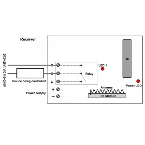
Here is the circuit diagram of receiver. You can connect runway light to “ B & C” terminal of receiver. Then supply power to receiver. When the transmitter is triggered by your controller box, it launch signal “ON” to receiver and relay to close. The runway lights will automatically turn on by wireless remote control; when the controller box is cut, the transmitter launch signal “OFF” to receiver and relay to open. The runway lights will automatically turn off by wireless remote control.
1_06
Finally you can also enter into the website and search the wireless remote control kit as following:
Website:
S1L-DC12-ANT2  CB-2V